# Helot (BMS100) Series Manual

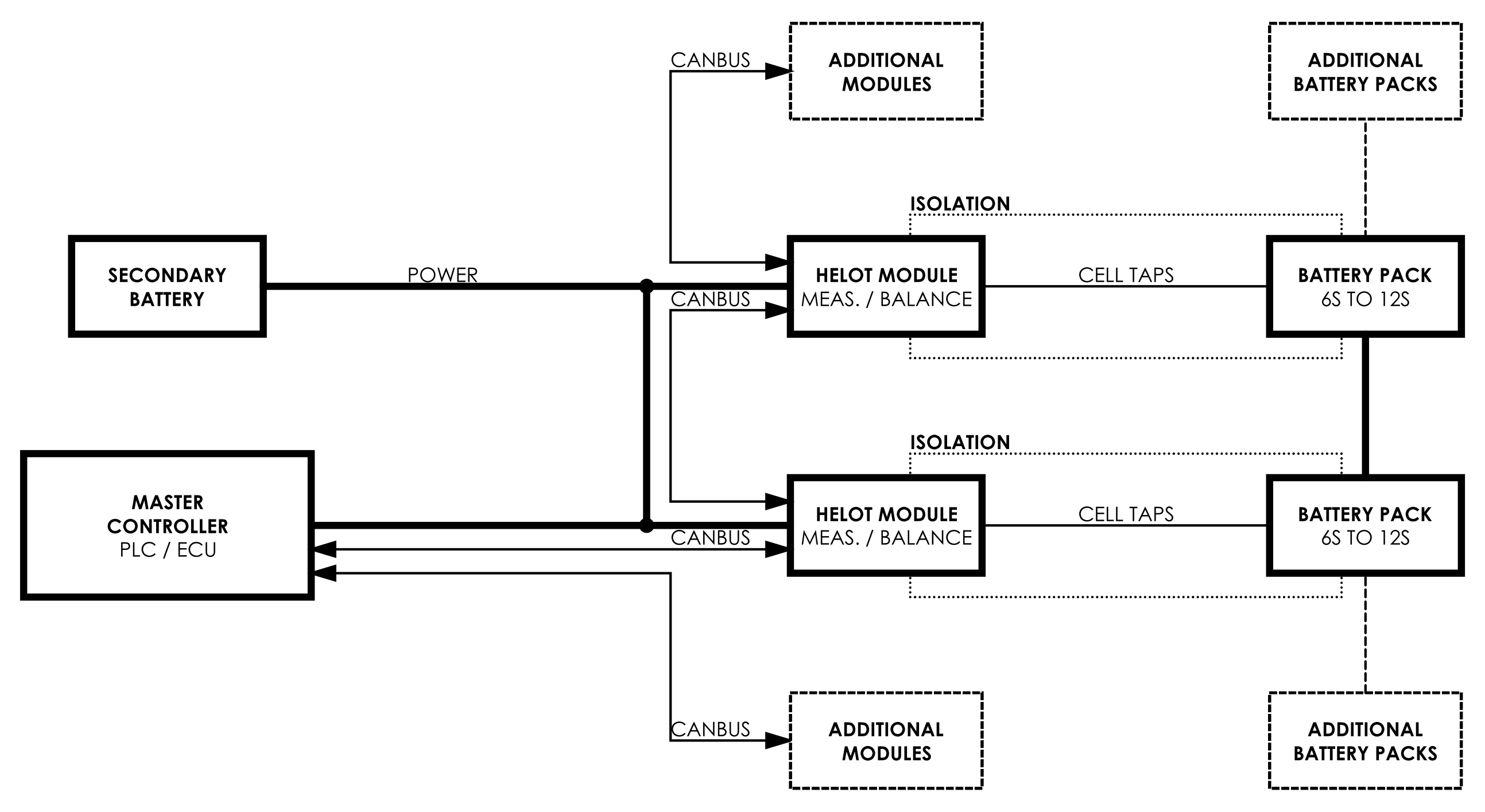
<figure><img src="https://2147680029-files.gitbook.io/~/files/v0/b/gitbook-x-prod.appspot.com/o/spaces%2F4cXJZdl4fi4k9oCd2oLR%2Fuploads%2FC794MEdXKmHLdFk5lE7u%2FBMS100%20System%20Overiew%20Diagram_22%20Mar%202024.png?alt=media&amp;token=b15b8f00-8a79-47b7-98fe-3dc38edc6305" alt=""><figcaption><p>BMS100 - System Overview Diagram</p></figcaption></figure>

## Overview

The Helot series are rugged battery monitoring modules designed specifically for light electric vehicles such as UxVs, e-mobility platforms and battery backup systems used in harsh environments.

Up to eight modules can be daisy-chained via a CAN network, providing deterministic measurement of individual cell voltages and cell group temperatures, as well as passive cell group shunt balancing for lithium-ion and lithium iron phosphate (LiFePO4) batteries.

The modules integrate with a master controller that sets the required shunt voltage, providing integrators flexibility to implement custom balancing algorithms.

Helot modules are small robust and reliable.

## Variants

Four different variants of the Helot series are available, for different series cell configurations:

–    BMS106 for 6 series cell packs.

–    BMS108 for 8 series cell packs.

–    BMS110 for 10 series cell packs.

–    BMS112 for 12 series cell packs.

## Features

### Status Indicators

Two status indicators provide status and diagnostics. Under fault conditions, the indicators flash in specific patterns to help diagnose module and battery faults without the need for additional external tools.

### Address Switch

A multi-position rotary switch provides eight unique addresses for the module’s CAN interface, allowing multiple modules to be connected to the same CAN bus.

### Interfaces

The modules have a Controller Area Network (CAN) interface that delivers cell voltage and temperature data to the master controller. The master sets a specific balance voltage for the Helot modules through a CAN frame command.&#x20;

The modules provide an interface to connect battery pack cell taps, and up to two external NTC temperature sensors. The interface provides the following functions:

–    Cell/pack voltage measurement.

–    Cell balancing (shunting).

–    Temperature measurement.

## Usage Disclaimer

{% hint style="danger" %}
CAETRON does not recommend the use of daisy-chained BMS100 series for battery packs with voltages above 120 V ripple-free d.c. as per the extra-low voltage definition in AS/NZS3000:2018.
{% endhint %}

It is the responsibility of the end user to determine the suitability of the BMS100 series for the target system, and the end user assumes all risks associated.

Installation of the BMS100 series should only be done by suitably qualified and experienced persons and the product should always be used within stated operating specifications.

CAETRON is not liable in case of damage or injury due to product misuse, failure, or unlawful use.


# Installation

## Installation Location

The BMS100 series are designed to be installed into a water and/or dust proof compartment within a vehicle or installation, close to battery packs.

The modules are designed to an IP30 ingress protection rating, reducing risk of damage to the internal electronics from handling and installation tooling.

{% hint style="info" %}
Risk of damage from temporary conductivity caused by pollution is reduced on the Helot modules by using conformal coating on the Printed Circuit Board Assembly (PCBA).
{% endhint %}

## Mounting

{% hint style="info" %}
All Helot (BMS100) series module variants have the same physical dimensions and mounting points.
{% endhint %}

### Fastening Hardware

The module is fastened to a mounting bracket or plate with four (4) **M3 socket head screws**.

### Mounting Outline

<figure><img src="https://2147680029-files.gitbook.io/~/files/v0/b/gitbook-x-prod.appspot.com/o/spaces%2F4cXJZdl4fi4k9oCd2oLR%2Fuploads%2Fd3b1kRzPxPRSv4CvWlTe%2FBMS100-mounting-outline_20%20Mar%202024.png?alt=media&amp;token=75692c02-1ad6-4005-8969-ab8c4291905b" alt=""><figcaption><p>BMS100 Module - Mounting Outline.</p></figcaption></figure>


# Interfaces & Wiring

## Safety Information

{% hint style="danger" %}
DO NOT CONNECT MODULE CELL INPUTS ACROSS MID-PACK SWITCHES, CONTACTORS OR SHUNTS
{% endhint %}

{% hint style="danger" %}
UNPLUG MODULE BATTERY CELL INTERFACES BEFORE BATTERY MAINTENANCE
{% endhint %}

{% hint style="danger" %}
VERIFY CELL VOLTAGES ON NEW INSTALLATIONS BEFORE CONNECTING TO MODULE
{% endhint %}

{% hint style="info" %}
All pinouts are looking into the module, "through" the wire housing.
{% endhint %}

## Isolation & Voltage Rating

The module is designed to provide a 1kV isolation barrier between the Battery Cell Interface J1 and the Power, CAN Interfaces J2/J3.

{% hint style="warning" %}
It is **not** recommended to connect GND to IGND, as this compromises the isolation barrier.
{% endhint %}

{% hint style="warning" %}
It is important to verify that other devices on the shared Power, CAN Interface are also isolated from the battery pack.
{% endhint %}

## J1 - Battery Cell Interface

### Wiring Considerations - Cell Taps

{% hint style="warning" %}
Correct wire selection is essential for mitigating the risk of cell tap shorts.
{% endhint %}

MPPE or PTFE insulated 24 to 20 AWG stranded wire is recommended. See [#tools-and-parts-battery-cell-interface](#tools-and-parts-battery-cell-interface "mention").

MPPE and PTFE provide good temperature and abrasion resistance.&#x20;

Cell tap wires must be routed correctly to ensure they do not chafe or rub against any objects that could cause abrasion, and are not near hot surfaces or flammable materials.&#x20;

It is recommended to keep cell tap wiring away from high current noisy conductors to minimise coupling and ensure good measurement accuracy.

### Temperature Sensors

Free hanging, insulated lead, two wire **10K 1% B25/85 3435K** NTCs are suitable, such as Vishay NTCLE and NTCA series.

{% hint style="info" %}
Ensure the correct crimps are used for the specific NTC's wire gauge.
{% endhint %}

### BMS106 Pinout

<figure><img src="https://2147680029-files.gitbook.io/~/files/v0/b/gitbook-x-prod.appspot.com/o/spaces%2F4cXJZdl4fi4k9oCd2oLR%2Fuploads%2FvnROhBGsyDpV8ItttlGA%2FUSER%20MANUAL%20DIAGRAMS%2C%20BMS112-J1%206S.png?alt=media&amp;token=cd253a68-5a40-4e5a-b872-a1a46de37a37" alt=""><figcaption><p>BMS106 J1 Pinout - Looking into module.</p></figcaption></figure>

### BMS108 Pinout

<figure><img src="https://2147680029-files.gitbook.io/~/files/v0/b/gitbook-x-prod.appspot.com/o/spaces%2F4cXJZdl4fi4k9oCd2oLR%2Fuploads%2Fl5h49vcFPSzoc0pj758w%2FUSER%20MANUAL%20DIAGRAMS%2C%20BMS112-J1%208S.png?alt=media&amp;token=e2db6b77-1fca-47ba-8b59-03fdb630d62a" alt=""><figcaption><p>BMS108 J1 Pinout - Looking into module.</p></figcaption></figure>

### BMS110 Pinout

<figure><img src="https://2147680029-files.gitbook.io/~/files/v0/b/gitbook-x-prod.appspot.com/o/spaces%2F4cXJZdl4fi4k9oCd2oLR%2Fuploads%2FpCnwEZ0pdSLdJJPXrRBd%2FUSER%20MANUAL%20DIAGRAMS%2C%20BMS112-J1%2010S.png?alt=media&amp;token=7a617a4c-ea2d-45b1-b644-13329364444c" alt=""><figcaption><p>BMS110 J1 Pinout - Looking into module.</p></figcaption></figure>

### BMS112 Pinout

<figure><img src="https://2147680029-files.gitbook.io/~/files/v0/b/gitbook-x-prod.appspot.com/o/spaces%2F4cXJZdl4fi4k9oCd2oLR%2Fuploads%2FhYIs8Jobr4FPrQ58ZjnS%2FUSER%20MANUAL%20DIAGRAMS%2C%20BMS112-J1%2012S.png?alt=media&amp;token=7544ecb9-e296-4034-ae27-0b1b3c62bda4" alt=""><figcaption><p>BMS112 J1 Pinout - Looking into module.</p></figcaption></figure>

### Signal Descriptions - Battery Cell Interface

| Pin Name          | Description       | Notes                        |
| ----------------- | ----------------- | ---------------------------- |
| CELL0 ... CELL12  | Battery Cell Taps | CELL0 is reference potential |
| NC                | No Connect        | **DO NOT CONNECT**           |
| RSVD              | Reserved          | **DO NOT CONNECT**           |
| VTEMP1 ... VTEMP2 | NTC Inputs        |                              |
| IGND              | NTC References    |                              |

### Tools & Parts - Battery Cell Interface

| Tool/Part                                | Manufacturer     | Manufacturer Part Number |
| ---------------------------------------- | ---------------- | ------------------------ |
| Header                                   | Wurth Elektronik | 66201821022              |
| Receptacle                               | Wurth Elektronik | 662018113322             |
| <p>Wire Crimps </p><p>(24 to 20 AWG)</p> | Wurth Elektronik | 66200113722DEC           |
| <p>Wire Crimps<br>(30 to 26 AWG)</p>     | Wurth Elektronik | 66200413722DEC           |
| Wire Crimp Tool                          | Wurth Elektronik | 600001                   |
| Wire Crimp Die                           | Wurth Elektronik | 600300300001             |
| <p>Wire</p><p>(or equivalent)</p>        | Alpha Wire       | 6713 OR                  |

## J2, J3 - Power, CAN Interface

{% hint style="info" %}
Power, CAN Interface pinouts are the same between all variants.
{% endhint %}

### Wiring Considerations - Power, CAN Interface

{% hint style="warning" %}
External devices connected to the module's Power, CAN Interface **must** share a common ground with the module.
{% endhint %}

Shielded, 4-wire, dual twisted pair, 20 to 24 AWG cable with 120 Ohm characteristic impedance is recommended. See [#tools-and-parts-power-can-interface](#tools-and-parts-power-can-interface "mention").

Shield termination and pass-through are available on the module, it is recommended to only terminate the shield to ground at a single point to avoid ground loops.

Due to the module's connector types an unshielded and untwisted section of the harness is inevitable. It is recommended to keep this section as short as possible.

Unshielded harnesses may work in certain low noise, short run installations, it is the integrator's responsibility to verify performance and integrity of the final wiring configuration.

<figure><img src="https://2147680029-files.gitbook.io/~/files/v0/b/gitbook-x-prod.appspot.com/o/spaces%2F4cXJZdl4fi4k9oCd2oLR%2Fuploads%2FENzhjgftr2XprPMWCd22%2FUSER%20MANUAL%20DIAGRAMS%2C%20BMS00-J2-J3.png?alt=media&amp;token=a2049766-0c4a-4c33-bf6a-1e48b00063eb" alt=""><figcaption><p>BMS100 J2 &#x26; J3 Pinouts - Looking into module.</p></figcaption></figure>

### Signal Descriptions - Power, CAN Interface

| Pin Name | Description                         | Notes                       |
| -------- | ----------------------------------- | --------------------------- |
| PWR      | <p>Module Power </p><p>(IN/OUT)</p> | 6 - 36VDC                   |
| GND      | Module Reference                    | Voltage bus return          |
| CANH     | CAN High                            |                             |
| CANL     | CAN Low                             |                             |
| CANL\_T  | CAN 120R Termination                | Connect to CAN Low          |
| SH       | Shield Pass-through                 | Connected between J2/J3     |
| SHGND    | Shield Termination                  | Internally connected to GND |

### Tools & Parts - Power, CAN Interface

| Tool/Part                           | Manufacturer     | Manufacturer Part Number |
| ----------------------------------- | ---------------- | ------------------------ |
| Header                              | Wurth Elektronik | 66200621022              |
| Receptacle                          | Wurth Elektronik | 662006113322             |
| Wire Crimps                         | Wurth Elektronik | 66200113722DEC           |
| Wire Crimp Tool                     | Wurth Elektronik | 600001                   |
| Wire Crimp Die                      | Wurth Elektronik | 600300300001             |
| <p>Cable </p><p>(or equivalent)</p> | LAPP             | 2170343                  |

###


# Indication & Configuration

<figure><img src="https://2147680029-files.gitbook.io/~/files/v0/b/gitbook-x-prod.appspot.com/o/spaces%2F4cXJZdl4fi4k9oCd2oLR%2Fuploads%2FLNTQAswi4LcRheuVNO4v%2FBMS100%20ISO%20CALLOUT.png?alt=media&amp;token=1ed0a11a-e46a-4229-8452-2abbf9f85b2c" alt=""><figcaption><p>BMS100 Series - Component Functions</p></figcaption></figure>

## Module Indicators

The module provides two visual indicators, allowing for quick visual identification of status and faults without the need for additional tools or adapters.

| YELLOW Indicator State | Module Status         |
| ---------------------- | --------------------- |
| OFF                    | NO POWER/MODULE FAULT |
| SOLID                  | POWERED/STANDBY       |
| FLASHING               | SHUNT(S) ACTIVE       |

| RED Indicator State | Fault                     |
| ------------------- | ------------------------- |
| OFF                 | NO FAULT                  |
| SOLID               | BATTERY FAULT             |
| FLASHING            | COMMUNICATION (CAN) FAULT |

## Module Addressing Scheme

The modules provide an eight (8) position rotary switch to set the internal CAN address.

Each rotary increment (0 to 7) increases the `module_address` of 300 by a factor of 10.

For example, a module with the rotary switch at 12 o'clock (position 0) would have a `module_address` of 300:

<pre><code><strong>module_address = 300 + 0 * 10 = 300
</strong></code></pre>

A module with the rotary switch at 9 o'clock (position 6) would have a `module_address` of 360:

```
module_address = 300 + 6 * 10 = 360
```

## Changing Address

If the module is powered, and the rotary switch position is changed the module will enter failsafe (YELLOW indicator off, RED indicator solid).&#x20;

This is implemented to ensure undetected dynamic CAN address changes during operation do not occur.

{% hint style="info" %}
To change address when the module is powered, adjust the rotary switch position, then press & release the reset button.
{% endhint %}

## Temperature Sensor Configuration

The modules contain an internal lookup table suitable for **10K B25/85 3435K** NTC thermistors, supporting a temperature range between -40C and 160C.

{% hint style="info" %}
CAETRON can offer custom lookup tables for other suitable temperature sensors if required.
{% endhint %}


# Functional Description

## CAN Communication

{% hint style="info" %}
The Helot series communication protocol is based upon a predicate protocol initially developed for Zeva's BMS Modules. Hence, Helot modules are designed to be drop-in replacements.
{% endhint %}

The module's standard bus speed is **250kbps**, frame format is **CAN 2.0B** using 29-bit ID's.

There are a total of five (5) different frame types:&#x20;

–    One (1) request data frame.

–    Four (4) response data frames.

### Request Data Frame (master/controller to BMS100 series module)

The master/controller sends the BMS100 series module a 2-byte request containing the desired **shunt voltage** in **16-bit big endian format**.

<table data-header-hidden><thead><tr><th width="112"></th><th></th></tr></thead><tbody><tr><td>ID</td><td>module_address + 0</td></tr><tr><td>BYTE 1</td><td>shunt voltage in millivolts, high byte</td></tr><tr><td>BYTE 2</td><td>shunt voltage in millivolts, low byte</td></tr></tbody></table>

{% hint style="info" %}
The module will inhibit shunting if the internal 1s timer elapses between CAN messages, or if the master/controller sends a requested shunt voltage of 0.
{% endhint %}

### 1st Response Data Frame 1 (BMS100 series module to master/controller)

After receiving a request data frame from the master/controller, the BMS100 series module will send four response frames in succession.&#x20;

The first being 8 bytes in size, containing the sampled **16-bit voltages 1 to 4, in millivolts -- big endian format.**

<table data-header-hidden><thead><tr><th width="111.5"></th><th></th></tr></thead><tbody><tr><td>ID</td><td>module_address + 1</td></tr><tr><td>BYTE 1</td><td>cell 1 voltage in millivolts, high byte</td></tr><tr><td>BYTE 2</td><td>cell 1 voltage in millivolts, low byte</td></tr><tr><td>BYTE 3</td><td>cell 2 voltage in millivolts, high byte</td></tr><tr><td>BYTE 4</td><td>cell 2 voltage in millivolts, low byte</td></tr><tr><td>BYTE 5</td><td>cell 3 voltage in millivolts, high byte</td></tr><tr><td>BYTE 6</td><td>cell 3 voltage in millivolts, low byte</td></tr><tr><td>BYTE 7</td><td>cell 4 voltage in millivolts, high byte</td></tr><tr><td>BYTE 8</td><td>cell 4 voltage in millivolts, low byte</td></tr></tbody></table>

### 2nd Response Data Frame (BMS100 series module to master/controller)

The second being 8 bytes in size, containing the sampled **16-bit voltages 5 to 8, in millivolts -- big endian format**.

<table data-header-hidden><thead><tr><th width="111.5"></th><th></th></tr></thead><tbody><tr><td>ID</td><td>module_address + 2</td></tr><tr><td>BYTE 1</td><td>cell 5 voltage in millivolts, high byte</td></tr><tr><td>BYTE 2</td><td>cell 5 voltage in millivolts, low byte</td></tr><tr><td>BYTE 3</td><td>cell 6 voltage in millivolts, high byte</td></tr><tr><td>BYTE 4</td><td>cell 6 voltage in millivolts, low byte</td></tr><tr><td>BYTE 5</td><td>cell 7 voltage in millivolts, high byte</td></tr><tr><td>BYTE 6</td><td>cell 7 voltage in millivolts, low byte</td></tr><tr><td>BYTE 7</td><td>cell 8 voltage in millivolts, high byte</td></tr><tr><td>BYTE 8</td><td>cell 8 voltage in millivolts, low byte</td></tr></tbody></table>

### 3rd Response Data Frame (BMS100 series module to master/controller)

The third being 8 bytes in size, containing the sampled **16-bit voltages 9 to 12, in millivolts -- big endian format.**

<table data-header-hidden><thead><tr><th width="113.5"></th><th></th></tr></thead><tbody><tr><td>ID</td><td>module_address + 3</td></tr><tr><td>BYTE 1</td><td>cell 9 voltage in millivolts, high byte</td></tr><tr><td>BYTE 2</td><td>cell 9 voltage in millivolts, low byte</td></tr><tr><td>BYTE 3</td><td>cell 10 voltage in millivolts, high byte</td></tr><tr><td>BYTE 4</td><td>cell 10 voltage in millivolts, low byte</td></tr><tr><td>BYTE 5</td><td>cell 11 voltage in millivolts, high byte</td></tr><tr><td>BYTE 6</td><td>cell 11 voltage in millivolts, low byte</td></tr><tr><td>BYTE 7</td><td>cell 12 voltage in millivolts, high byte</td></tr><tr><td>BYTE 8</td><td>cell 12 voltage in millivolts, low byte</td></tr></tbody></table>

### 4th Response Data Frame (BMS100 series module to master/controller)

The fourth being 2 bytes in size, containing the sampled **8-bit temperatures, with a +40C offset.**

<table data-header-hidden><thead><tr><th width="106.5"></th><th></th></tr></thead><tbody><tr><td>ID</td><td>module_address + 4</td></tr><tr><td>BYTE 1</td><td>temperature 1 in degrees celcius (+40)</td></tr><tr><td>BYTE 2</td><td>temperature 2 in degrees celcius (+40)</td></tr></tbody></table>

{% hint style="info" %}
The master/controller logic must subtract 40 from each temperature for actual values.
{% endhint %}

### Variants

The same request/response packet structure is used across all variants.&#x20;

{% hint style="info" %}
For variants <12S, the unused bytes are zeroed.
{% endhint %}

<table><thead><tr><th width="228">PACKET/BYTE</th><th width="130">12S</th><th width="128">10S</th><th width="130">8S</th><th>6S</th></tr></thead><tbody><tr><td>module_address + 1 / 1</td><td>cell 1 H</td><td>cell 1 H</td><td>cell 1 H</td><td>cell 1 H</td></tr><tr><td>module_address + 1 / 2</td><td>cell 1 L</td><td>cell 1 L</td><td>cell 1 L</td><td>cell 1 L</td></tr><tr><td>module_address + 1 / 3</td><td>cell 2 H</td><td>cell 2 H</td><td>cell 2 H</td><td>cell 2 H</td></tr><tr><td>module_address + 1 / 4</td><td>cell 2 L</td><td>cell 2 L</td><td>cell 2 L</td><td>cell 2 L</td></tr><tr><td>module_address + 1 / 5</td><td>cell 3 H</td><td>cell 3 H</td><td>cell 3 H</td><td>cell 3 H</td></tr><tr><td>module_address + 1 / 6</td><td>cell 3 L</td><td>cell 3 L</td><td>cell 3 L</td><td>cell 3 L</td></tr><tr><td>module_address + 1 / 7</td><td>cell 4 H</td><td>cell 4 H</td><td>cell 4 H</td><td>cell 4 H</td></tr><tr><td>module_address + 1 / 8</td><td>cell 4 L</td><td>cell 4 L</td><td>cell 4 L</td><td>cell 4 L</td></tr><tr><td>module_address + 2 / 1</td><td>cell 5 H</td><td>cell 5 H</td><td>cell 5 H</td><td>cell 5 H</td></tr><tr><td>module_address + 2 / 2</td><td>cell 5 L</td><td>cell 5 L</td><td>cell 5 L</td><td>cell 5 L</td></tr><tr><td>module_address + 2 / 3</td><td>cell 6 H</td><td>cell 6 H</td><td>cell 6 H</td><td>cell 6 H</td></tr><tr><td>module_address + 2 / 4</td><td>cell 6 L</td><td>cell 6 L</td><td>cell 6 L</td><td>cell 6 L</td></tr><tr><td>module_address + 2 / 5</td><td>cell 7 H</td><td>cell 7 H</td><td>cell 7 H</td><td>0</td></tr><tr><td>module_address + 2 / 6</td><td>cell 7 L</td><td>cell 7 L</td><td>cell 7 L</td><td>0</td></tr><tr><td>module_address + 2 / 7</td><td>cell 8 H</td><td>cell 8 H</td><td>cell 8 H</td><td>0</td></tr><tr><td>module_address + 2 / 8</td><td>cell 8 L</td><td>cell 8 L</td><td>cell 8 L</td><td>0</td></tr><tr><td>module_address + 3 / 1</td><td>cell 9 H</td><td>cell 9 H</td><td>0</td><td>0</td></tr><tr><td>module_address + 3 / 2</td><td>cell 9 L</td><td>cell 9 L</td><td>0</td><td>0</td></tr><tr><td>module_address + 3 / 3</td><td>cell 10 H</td><td>cell 10 H</td><td>0</td><td>0</td></tr><tr><td>module_address + 3 / 4</td><td>cell 10 L</td><td>cell 10 L</td><td>0</td><td>0</td></tr><tr><td>module_address + 3 / 5</td><td>cell 11 H</td><td>0</td><td>0</td><td>0</td></tr><tr><td>module_address + 3 / 6</td><td>cell 11 L</td><td>0</td><td>0</td><td>0</td></tr><tr><td>module_address + 3 / 7</td><td>cell 12 H</td><td>0</td><td>0</td><td>0</td></tr><tr><td>module_address + 3 / 8</td><td>cell 12 L</td><td>0</td><td>0</td><td>0</td></tr></tbody></table>

## Cell Balancing

The module will enable shunts across cells that exceed the requested **shunt voltage** received from the master/controller.&#x20;

This will continue until the internal 1s timer elapses between CAN messages **or** until the cell voltage is below the requested **shunt voltage**.

{% hint style="info" %}
A master/controller request rate of 2 Hz is recommended for reliable continuous balancing.
{% endhint %}


# Internal Circuits

## Power, CAN Block Diagram

The Helot modules contain transient voltage suppression and reverse polarity protection. An internal fuse is included between the +VSUPPLY bus and the module power circuitry to reduce the risk of a faulty module taking down the entire bus and other connected devices.

<figure><img src="https://2147680029-files.gitbook.io/~/files/v0/b/gitbook-x-prod.appspot.com/o/spaces%2F4cXJZdl4fi4k9oCd2oLR%2Fuploads%2FT61GnpHk9IxdjpyPYb8z%2FBMS100%20Power%2C%20CAN%20Block%20Diagram_22%20Mar%202024.png?alt=media&amp;token=26bf417b-1120-45e5-ab39-9304f35a46da" alt=""><figcaption><p>BMS100 - Power, CAN Block Diagram</p></figcaption></figure>

## Isolation Block Diagram

The modules are designed to provide 1kV of isolation between the Power, CAN Interface (J2/J3) and the Battery Cell Interface (J1). This isolation is implemented with two digital isolators spanning the GND and IGND references, between the MCU and Battery ASIC.

<figure><img src="https://2147680029-files.gitbook.io/~/files/v0/b/gitbook-x-prod.appspot.com/o/spaces%2F4cXJZdl4fi4k9oCd2oLR%2Fuploads%2FytnThxdCX5knZeteEoiv%2FBMS100%20Isolation%20Block%20Diagram_22%20Mar%202024.png?alt=media&amp;token=d9d06605-8c5d-4b28-84fb-f8cb32976e4c" alt=""><figcaption><p>BMS100 - Isolation Block Diagram</p></figcaption></figure>

## Balancing Front-end Circuit Diagram

All cell tap interfaces are fused ([Bel Fuse C2Q-250](https://www.belfuse.com/product/part-details?partn=C2Q-250)) to mitigate the risk of cell damage in the event of an internal module failure or short circuit. 47 Ohm, automotive grade pulse withstanding resistors are used for dissipative shunting of cell currents.

<figure><img src="https://2147680029-files.gitbook.io/~/files/v0/b/gitbook-x-prod.appspot.com/o/spaces%2F4cXJZdl4fi4k9oCd2oLR%2Fuploads%2FeMnvxlQXpoI74PZTpXvj%2FBMS100%20Balancing%20Front-end%20Circuit%20Diagram_22%20Mar%202024.png?alt=media&amp;token=61c00cfe-ebe9-4883-8a4c-e852dfde9fd1" alt="" width="563"><figcaption><p>BMS100 - Balancing Front-end Circuit Diagram</p></figcaption></figure>

## NTC Input Circuit Diagram

The internal Battery ASIC provides a switched +2.5V reference bias, via a 10K pull-up for each of the two (2) external NTC temperature sensors.

{% hint style="warning" %}
Never injected voltage into the VTEMP pins, as it may damage the internal circuitry.
{% endhint %}

<figure><img src="https://2147680029-files.gitbook.io/~/files/v0/b/gitbook-x-prod.appspot.com/o/spaces%2F4cXJZdl4fi4k9oCd2oLR%2Fuploads%2FukwYVnUVQYcxK7yr7p60%2FBMS100%20NTC%20Circuit%20Diagram_22%20Mar%202024.png?alt=media&amp;token=ae785f7a-ea8e-4d99-b5b7-d9d5c0bead07" alt="" width="563"><figcaption><p>BMS100 - NTC Input Circuit Diagram</p></figcaption></figure>


# Specifications

## Mechanical & Environmental

<table data-header-hidden><thead><tr><th width="338"></th><th></th></tr></thead><tbody><tr><td>DIMENSIONS</td><td>120.8 x 65 x 18.9 mm</td></tr><tr><td>WEIGHT</td><td>100 grams</td></tr><tr><td>OPERATING TEMPERATURE</td><td>-40 to 85C</td></tr><tr><td>INGRESS PROTECTION</td><td>IP30</td></tr></tbody></table>

## Electrical & Interfaces

<table data-header-hidden><thead><tr><th width="333"></th><th></th></tr></thead><tbody><tr><td>INPUT VOLTAGE RANGE</td><td>0 to 36V</td></tr><tr><td>POWER CONSUMPTION (IDLE)</td><td>100mW</td></tr><tr><td>CELL QUIESCENT DRAW</td><td>400uA</td></tr><tr><td>SUPPORTED CHEMISTRIES</td><td>Li-ion, LiFePO4</td></tr><tr><td>CELLS</td><td>6S to 12S</td></tr><tr><td>CELL MEASUREMENT RANGE</td><td>0 to 5000mV</td></tr><tr><td>CELL MEASUREMENT ACCURACY</td><td>≤10mV</td></tr><tr><td>PACK VOLTAGE</td><td>14.4 to 60V</td></tr><tr><td>TEMPERATURE SENSE (DUAL)</td><td>100K B25/85 4190K</td></tr><tr><td>COMMUNICATION</td><td>250kpbs CAN 2.0B</td></tr><tr><td>BALANCING</td><td>Passive, 47Ω Shunts</td></tr><tr><td>ISOLATION</td><td>1kV</td></tr></tbody></table>


